 Loading... Please wait...

- Home
- INSTALLATION AND Q&A
- CONNECTOR INSTALLATION INSTRUCTIONS
CONNECTOR INSTALLATION INSTRUCTIONS
-
The trimming instructions for the 42/43/43X & 48 using a PRO connector are very different. Please take a look at the product specific instruction on web or inside the insert of the actual product.
- On Gen 5 and 42/43/43X/48 You will only have two pins to remove and the trigger spring has been eliminated for a leaf style spring.
EVO ELITE, PRO 3.3, ROCKET, TACTICAL & ALL OTHER TRIGGER CONNECTOR INSTALLATION INSTRUCTIONS
Introduction
-
The GHOST EVO ELITE, PRO 3.3, ROCKET & TACTICAL are not "Drop In "parts they are fitted by shortening the Trigger Control Tab/Stop (TCT) of the EVO ELITE, PRO 3.3, ROCKET or TACTICAL.
-
No Changes are made to the Glock Pistol. To do the installation please perform all the steps in SECTIONS I through IV (For Drop-in Triggers Use SECTION I and Reassemble).
-
The GHOST 3.5 LB. TRIGGER, 3.5 LB. ULTIMATE, EDGE 3.5, 4.5 LB. RANGER & 5.0 LB. PATROL are drop-in trigger connectors. Drop-in means there is NO fitting required.
-
You do not have to remove any material for these trigger connectors to function properly. To do the installation please perform all the steps in SECTION I.
The PART is modified not the Glock.
Please read these instructions completely before beginning.
The uh-oh Notice:
-
If you installed the Evo Elite, PRO 3.3, Rocket or Tactical before you shortened the Trigger Control Tab/Stop (TCT) as recommended in SECTION II: INSTALLATION EVO ELITE, PRO 3.3, ROCKET & TACTICAL
-
And your pistol will not fire therefore you will not be able to disassemble your pistol (normal disassembly procedures require you fire your empty pistol so that you may remove the slide, you can not disassemble a cocked pistol).
-
Because the Trigger Control Tab/Stop (TCT) on the Evo Elite, PRO 3.3, Rocket or Tactical is limiting the rearward movement of the trigger you must remove the firing pin assembly to disassemble your pistol so that you can remove the slide assembly.
-
Please see number 4 in Section II. Once the slide is removed you may begin in Section II.
NOTE:
-
These connectors were designed for PRACTICAL, TACTICAL & SELF DEFENSE use.
-
You may use the GHOST EVO ELITE, GHOST PRO 3.3, GHOST ROCKET & GHOST TACTICAL for self-defense/tactical applications.
-
If you want a heavier trigger pull you may replace the Glock coil trigger spring with an Olive Glock New York Trigger Spring. A Glock Armorer or Gunsmith should install these parts but anyone can do it.
-
The installation and fitting are not difficult if the instructions are followed by the numbers and you take your time.
Recommended Equipment:
-
Clear slide cover plate (our customers feedback says you must get the fitting clear plate!) or sectioned standard slide plate cover
-
3/32nd punch or Glock Armorer's Tool
-
Dremel tool or grinder
-
A buffing wheel


CLICK ON ITEMS TO PURCHASE
SECTION I: PISTOL DISASSEMBLY
1. Unload the Glock Pistol
- Verify it is unloaded!
2. Remove the Slide
- Use an owners manual or Armorer's manual for reference for names/depictions of the parts.
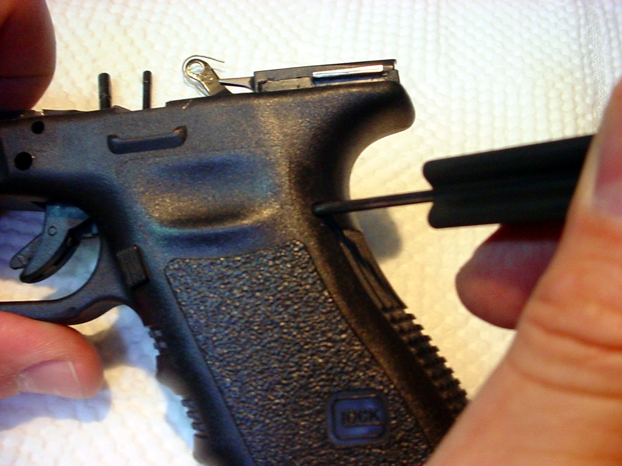
3. Locking Block Pin Removal
- Glock pistols have two or three frame pins they are:
- locking block pin,
- trigger pin &
- trigger mechanism housing pin
-
First using a 3/32's of an inch punch from the left side (the side the slide stop is on) of the receiver, push the locking block pin (the top pin) out of the receiver to the right all pins are removed from left to right.
-
If your pistol has two pins proceed to number 4.
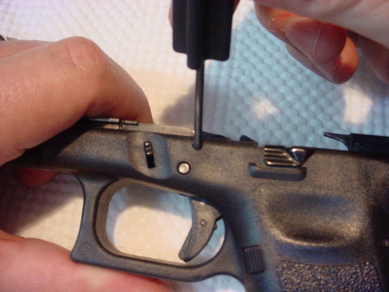
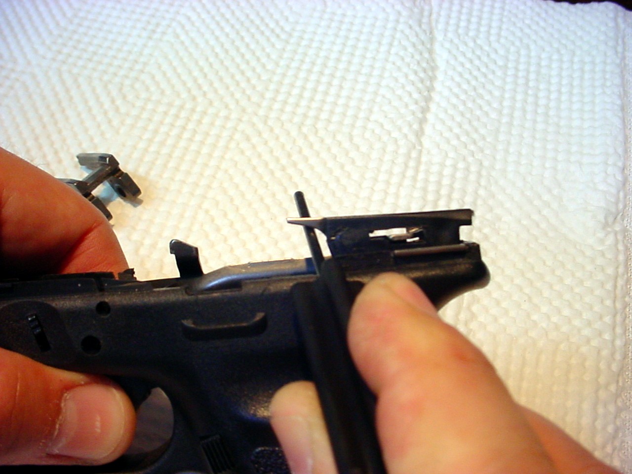
4. Trigger Pin Removal
-
This is the trickiest part of the process because with one hand you have to move the slide stop up/down & front/rear while using the punch in your other hand to firmly press the trigger pin out of the receiver from left to right (sometimes by moving the trigger forward it makes this step easier).
-
If you moved the pin into the frame slightly but it does not push out it is best to push the pin back in from the right side and try again.
-
Be patient!
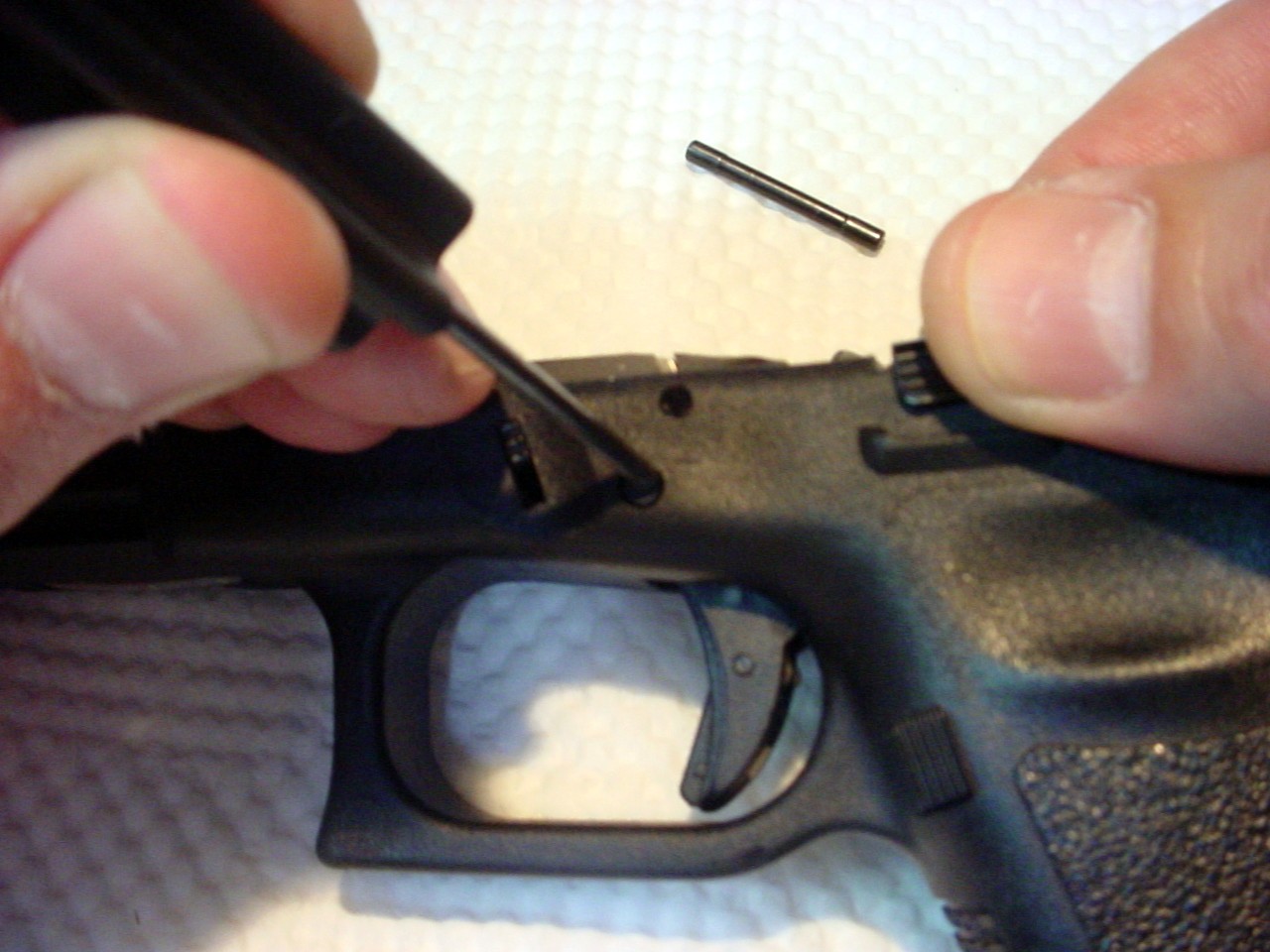
5. Slide Stop Removal
- When the trigger pin is pushed out the right side of the receiver the slide stop will lift out of the receiver.
6. Locking Block Removal
- Using your punch insert the tip under the locking block and apply downward pressure moving the locking block up and out of the receiver.
7. Trigger Housing Pin Removal
- Using your punch push the trigger mechanism housing pin out of the receiver from left to right.
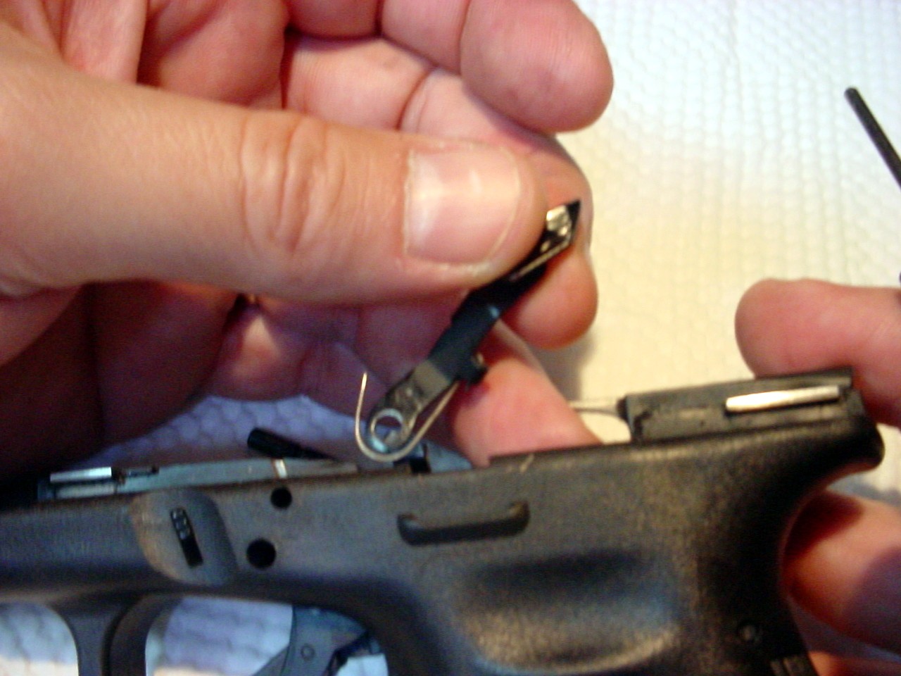
8. Trigger Assembly Removal
-
Use your punch and place it under the ejector mounted in the trigger housing.
-
Apply upward pressure lifting the trigger housing up and out of the receiver.

9. Separating the Trigger with Trigger Bar from the Trigger Housing
-
Pull forward on the trigger with trigger bar while rotating the trigger bar counterclockwise.
-
You may now lift the trigger bar out of the trigger housing.
-
The trigger coil spring is still attached.
-
Unhook the spring from the trigger bar.
-
Note how it attaches to the trigger bar.
-
Looking from the right side it attaches to form an "s".
-
The top of the "s" is hooked to the trigger bar and the bottom of the "s" is hooked to the trigger housing.
-
The spring must be reattached in this manner for the pistol to function properly.
10. Removal of the Connector
-
The best way to remove the connector is to use another connector by pushing one connector out of the trigger housing with the other.
-
Using the long mounting tab on the bottom of the connector.
-
Insert the connector into the rectangular slot of the trigger housing located on the ejector side of the housing.
-
Push the installed connector out of the housing.
-
Do not bend or attempt to pry the connector out of the housing. It may break.
Note: If installing a drop-in trigger connector, replace the removed connector with the drop-in one and push the lower part of the connector flush with the trigger mechanism housing. -
Reverse the steps and reassemble the pistol.
-
Dry-fire and functions check.
-
Please see SECTION III: TROUBLESHOOTING
SECTION II: INSTALLATION EVO ELITE, PRO 3.3, ROCKET & TACTICAL
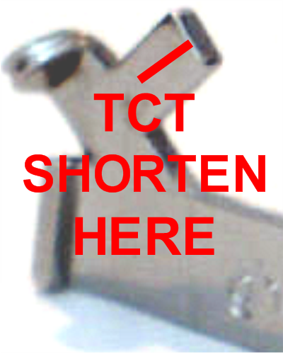
The EVO ELITE, PRO 3.3, ROCKET & TACTICAL are fitted to stop this excess trigger movement by gradually shortening Trigger Control Tab/Stop (TCT).
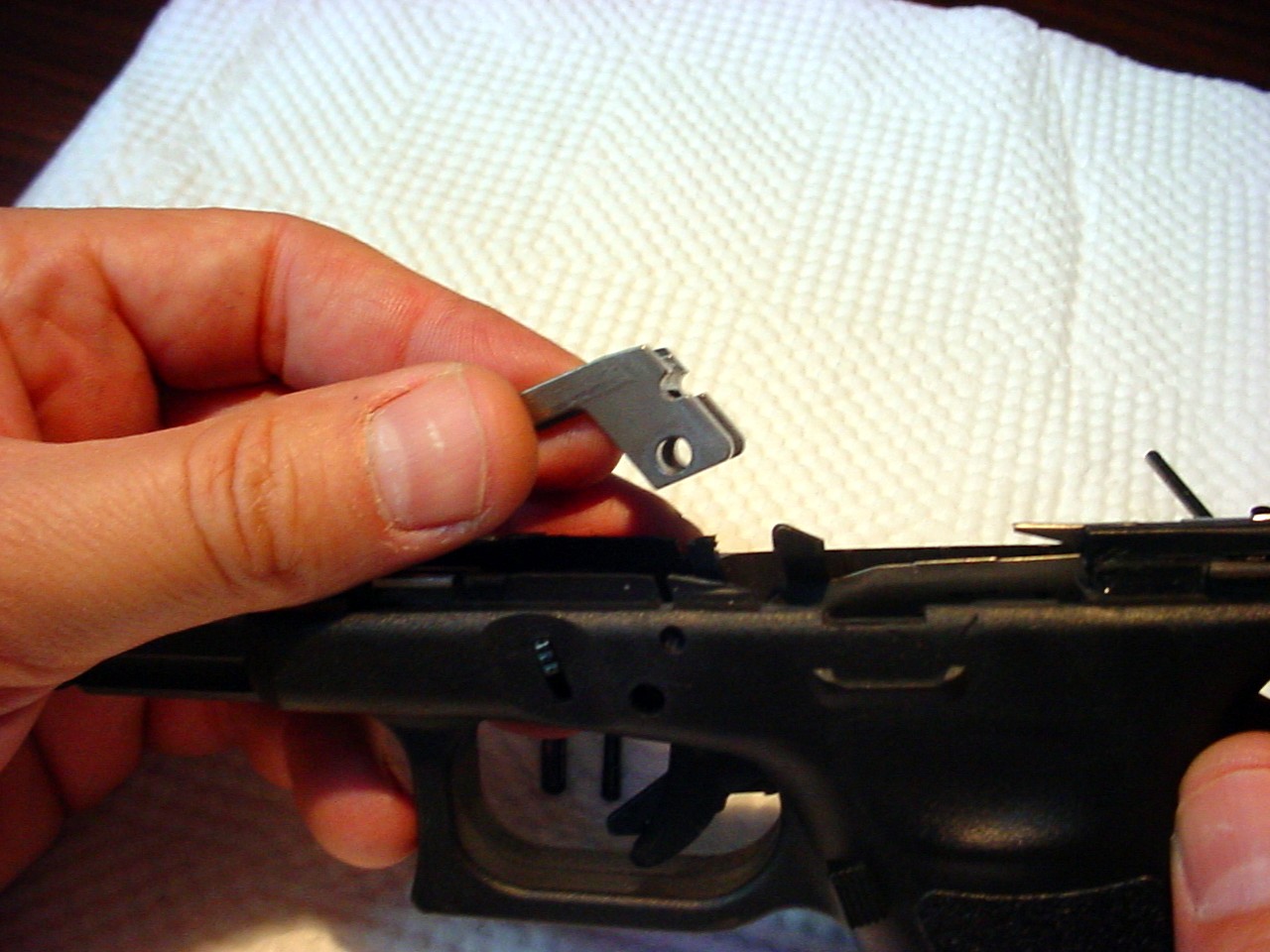
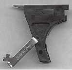
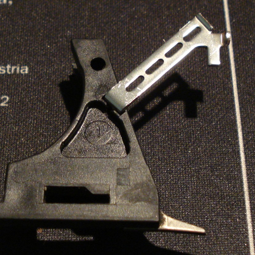
1. The ROCKET/TACTICAL is depicted above.
-
Notice the additional tab on the part.
-
This tab is the Trigger Control Tab/Stop (TCT).
-
This is the portion you will gradually shorten to affect your triggers over-travel and reset. Do not alter or shorten the other surfaces or tabs on the connector.
-
The end of the stop should only contact the trigger bar immediately after the pistol fires.
2. Insert the EVO ELITE/PRO 3.3/ROCKET/TACTICAL Connector
-
Insert the EVO ELITE/PRO 3.3/ROCKET/TACTICAL Connector into the trigger housing and press it into the housing so that the base of the connector is flush against the housing.
-
Reinstall the trigger coil spring on the trigger with bar. Reinsert the trigger with bar back into the trigger housing.
- Note:
-
When you press the connector into the housing ensure that bottom portion that is mounted in the trigger mechanism housing sits slightly below flush in the trigger mechanism housing.
-
Check the outward bend angle of the connector. This is done by sliding a piece of (.003 or standard 20 lb paper) paper between the connector and the top portion of the trigger mechanism housing. The paper should slide through with a little resistance. If the paper does not slide through, then the connector needs to be removed and bent out ever so slightly. If it slides through with no resistance the connector needs to be removed and bent in ever so slightly.
-Measuring the bend angle-

-Checking the bend angle with a sheet of paper-
-Adjusting the bend angle-
-
The connector being bent too far inwards is the most common customer problem. The connectors are modeled after the Glock connectors.
-
There are slight variances in the trigger mechanism housings which can affect the final bend angles.
-
Please use the technique above to insure your connector bend angle is correct.
-
Take a look at your current angle before starting the adjustment so you can compare and know if you have moved it to the direction you intended to move it to.
-
You will need to tug or press the connector to adjust it.
-
Remember you do not want to take pliers or a vice to do this adjustment. This is a normal adjustment that will not affect the reliability of your weapon in any way.
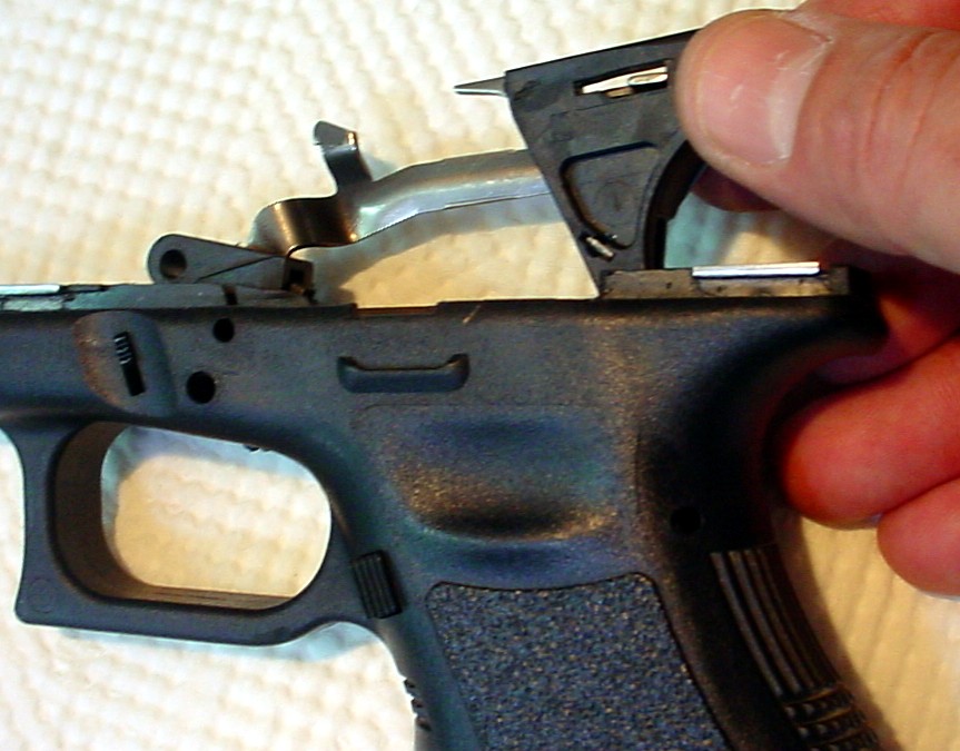
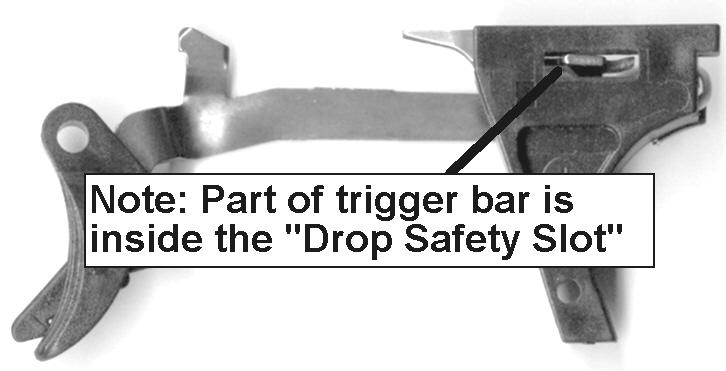
3. The TCT is longer than necessary to enable greater adjustment.
-
The tab keeps part of the trigger inside the drop safety slot of the trigger housing (arrow). When the trigger is in this position you will not be able to push it down to release the firing pin for disassembly/removal of the slide.
-
Visually determine the amount to be removed from the TCT on the EVO ELITE/PRO 3.3/ROCKET/TACTICAL. This is determined by how much of the trigger bar is in the drop safety slot. Take your time and gradually shorten the stop tab. You may use a file, grinding wheel or Dremel with a cutting wheel (use the cutting wheel as a grinder see 4f below).
A. Determining Amount of Initial Tab Shortening
- Shorten the TCT just enough so that the trigger may move rearward slightly out of the drop safety slot.
- This will ensure that once the pistol is reassembled you will be able to push down on the trigger bar to release the firing pin once the housing is reinstalled in the pistol.
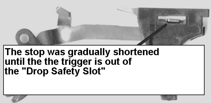
B. Tab Was Gradually Shortened

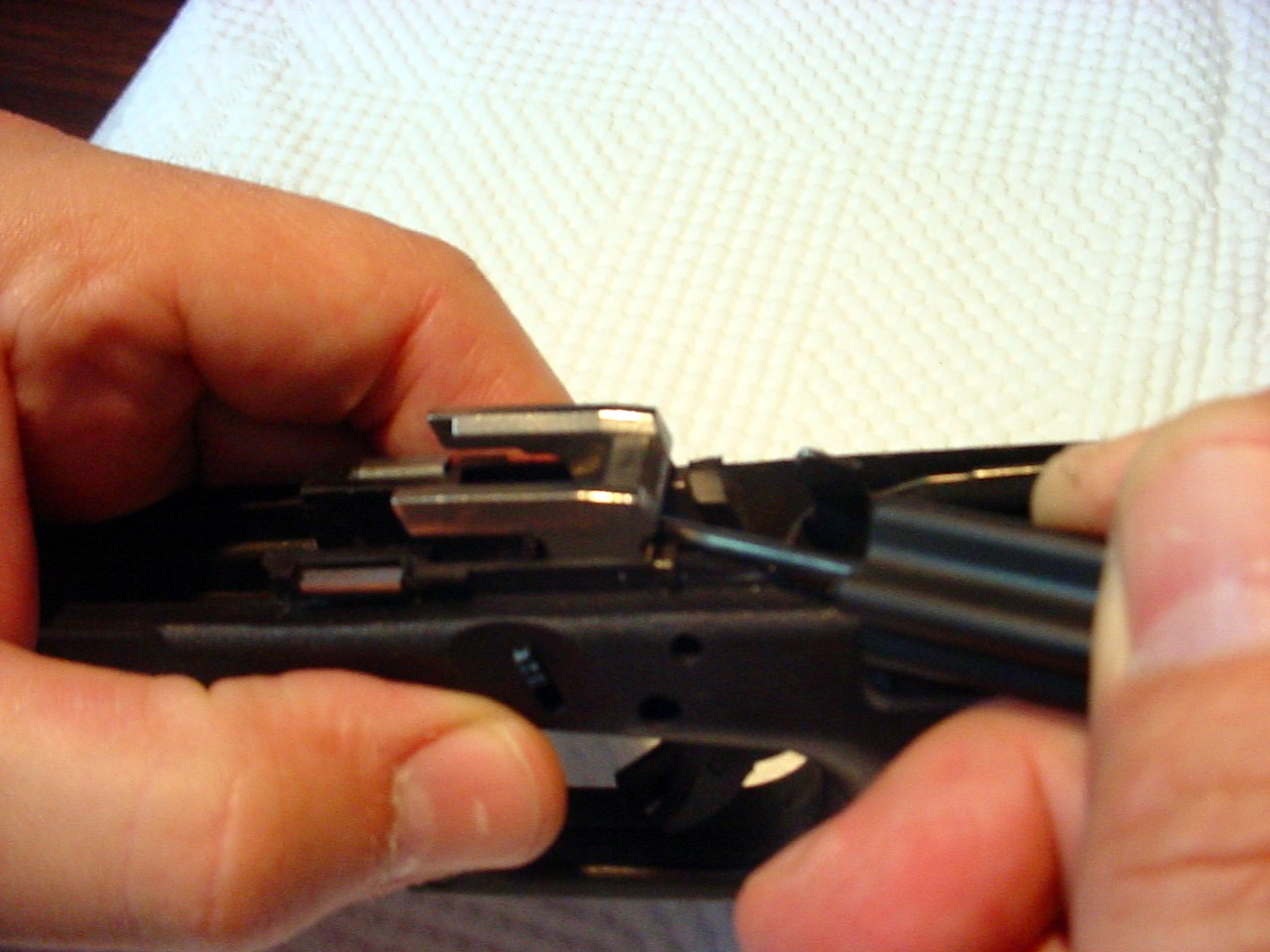
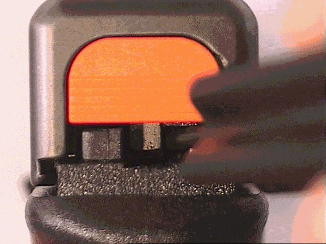
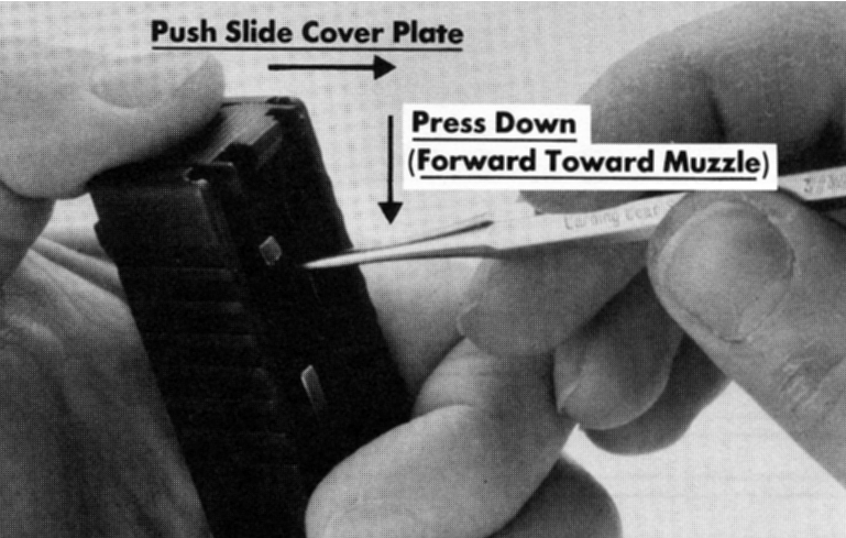
4. Slide Plate Removal
A. Remove the standard slide plate by depressing the spacer sleeve (the black plastic ring looking thing in front of the firing pin leg in the firing pin channel on the underside of the slide) towards the muzzle as depicted in the top picture below.
- Keep your thumb over the slide cover plate as you slide the cover plate down out of the slide. Use caution because the spring-loaded bearing shown in the second picture below may shoot out of the slide.
- Install a Ghost Armorer's Plate Clear Armorer Slide Cover Plate by depressing the spacer sleeve (the first object the cover plate contacts) next depress the spring-loaded bearing and slide the cover plate all the way up until it stops.
B. Reassemble the pistol by reversing the disassembly instructions except put the locking block pin in first. If the pistol will not fire after reassembly.
- This is because the TCT is too long and does not permit the trigger bar to travel far enough to the rear to release the firing pin.
- This is a good thing. Now you can adjust the TCT by gradually shortening it to exactly the trigger feel desired.
![]()
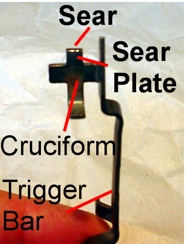
C. Determining sear & firing pin contact.
- Use the clear slide cover plate and visually determine how much farther the trigger bar/sear (the sear is the rearmost part of the sear plate pictured above.
- The sear contacts the firing pin.) must travel to the rear to release the firing pin.
- Once you have determined this distance remove half that amount from the TCT (the trigger is a lever and moves the bar a greater distance on the rear end).
- This is determined by the thickness of the sear that is contacting and holding the firing pin to the rear.
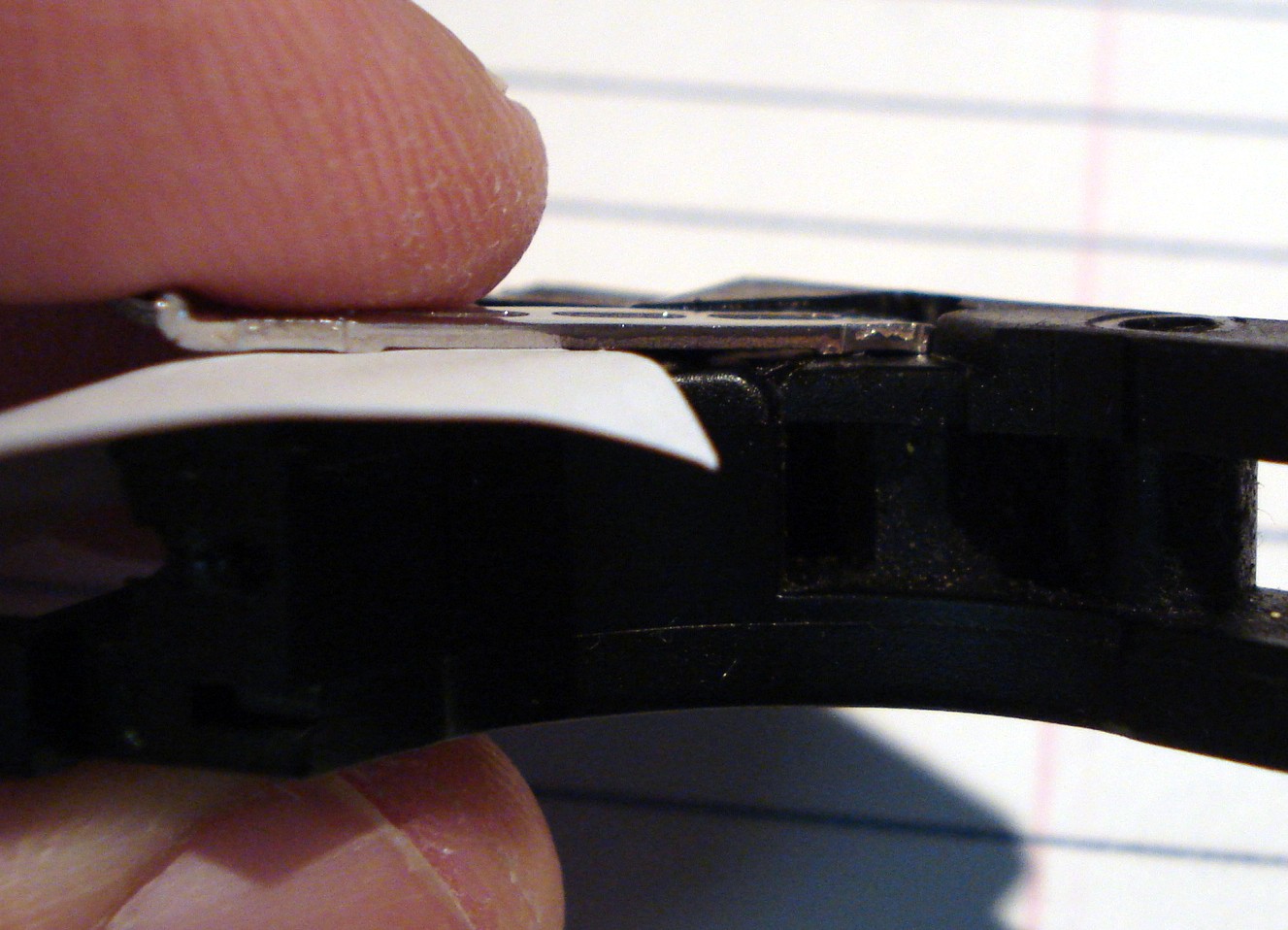
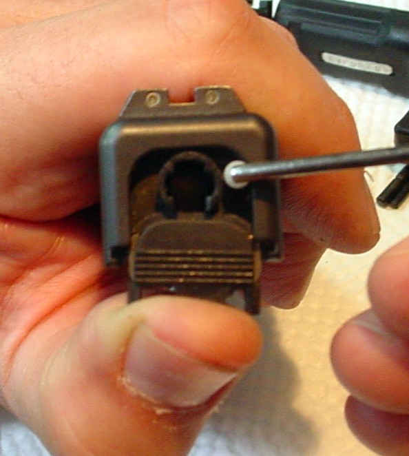
D. Insert your Armorer's tool/punch under the slide cover plate but on top of the trigger bar and press down on the trigger bar while pressing and holding the trigger to the rear.
- This will release the firing pin.
4D. Pushing down on the trigger bar
NOTE:
-
If you do not have a clear plate or orange plate which would enable you to push down on the trigger bar to release the firing pin (see photo 4 d.) so you can remove the slide and disassemble the pistol.
-
Then you may have to remove the slide cover plate and the firing pin assembly to remove the slide from the pistol (See above).
This is because if the pistol is not dry fired you cannot remove the slide because the firing pin is being held by the trigger with the bar which cannot be moved to the rear because the TCT is too long (see photo 3 a.) -
To remove the slide cover plate, see photos # 4 above.
-
To remove the firing pin assembly, pull entire assembly out of the opening created by the removal of the slide cover plate.
E. Remove Trigger House
- Next you will remove the trigger housing and trigger with bar.
F. Shorten the Stop Gradually
-
Next you will have to very gradually shorten the stop (usually .01 or about the thickness of a business card) reinstall and reassemble the pistol to try it again. You may use the trigger housing as a holder.
-
Repeat this process-until you are satisfied that your trigger is perfect for you.
-
You may have to do these many times (it's worth the effort). This way you will get an incredible trigger pull and reset!
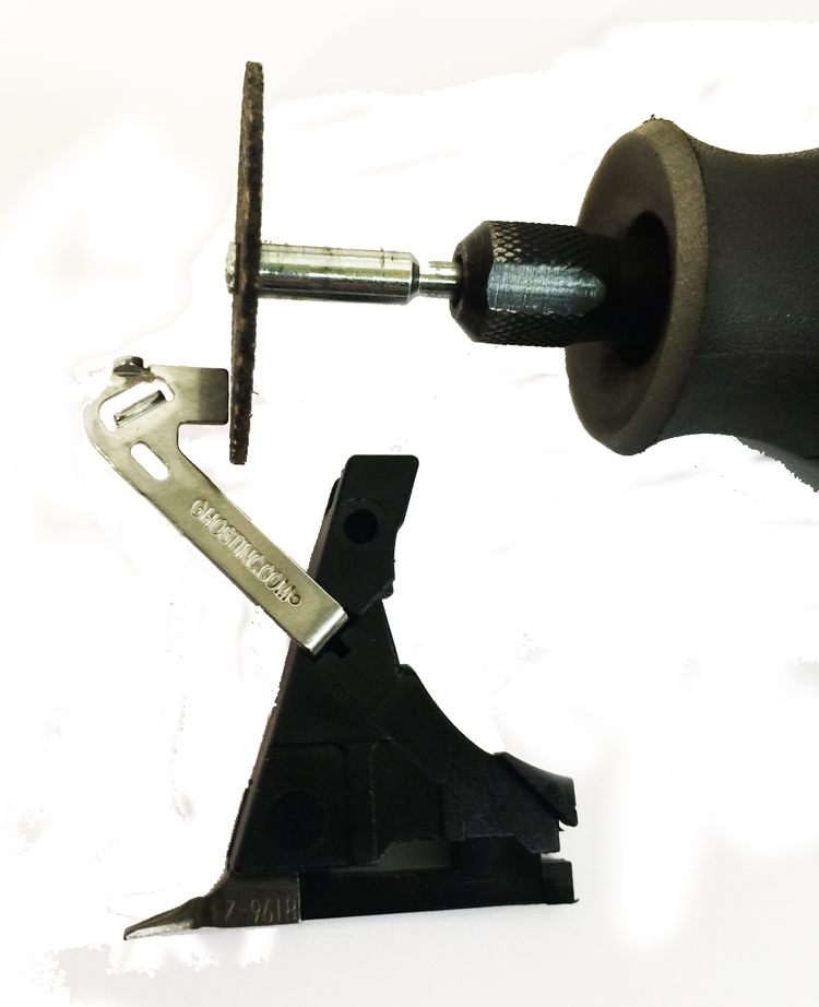
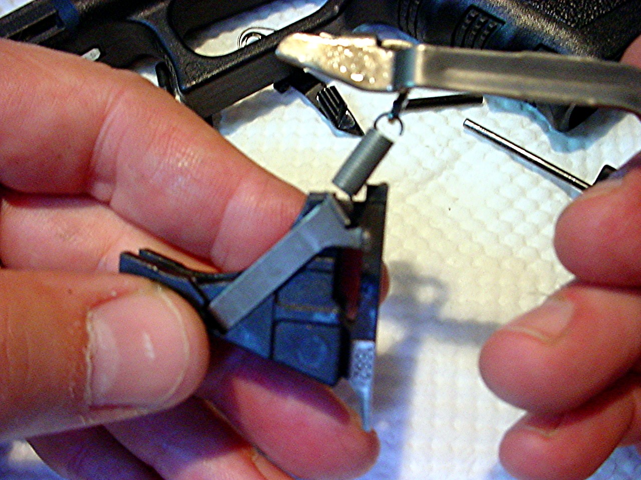
4F. Gradually shortening the stop tab - using the trigger mechanism
housing as a holder, press the connector to the secured cutting implement -
a Dremel or Bench Grinder
5. Polishing the Stop
-
Once you have the EVO ELITE/PRO 3.3/ROCKET/TACTICAL shortened to the optimum length for your Glock you should polish the end of the stop so that it is smooth (use a buffing wheel or fine/polishing stone).
-
Finally remove all roughness from around the end of the stop (if you use a file do not let the file contact the parts of the connector stop that will contact the trigger bar-if you do you must polish off the burrs).
6. The pistol should fire positively.
-
There should be no hesitation once the trigger is pulled to release the firing pin and once the firing pin is released the trigger should stop.
-
If the pistol is going to be used for duty or self-defense you may want to remove an extra .01 of an inch from the tab for an extra margin of safety.
NOTE:
You may shorten the TCT to your liking, you will not damage the trigger connector you are just adding more over-travel.
7. Lubricate & Perform the Glock
-
Lubricate and perform the Glock recommended functions.
-
Check on the unloaded pistol.
-
Ensure the pistol fires and resets.
-
Test live fire the pistol at a range.
IMPORTANT!!
IF THE PISTOL IS USED FOR DUTY OR SELF DEFENSE FIRE AT LEAST 300 ROUNDS OF
THE AMMO TO BE USED FOR THESE PURPOSES TO INSURE PROPER FUNCTIONING.
SECTION III: TROUBLE SHOOTING
PROBLEM: Pistol does not fire
SOLUTION: TCT is too long or connector is bent too far inwards. Shorten TCT or bend connector outwards.
PROBLEM: Pistol fires sluggishly
SOLUTION: TCT maybe too long. Shorten TCT.
PROBLEM: Trigger does not reset or resets with a quieter than normal (a slight muted click) "click".
SOLUTION: Connector maybe bent too far inwards. SEE SECTION II #2 Note: 2.
PROBLEM: Trigger resets with a louder than normal "click” and there is a noticeable increase dragging on the slide when operated.
SOLUTION: Connector maybe bent too far outwards. SEE SECTION II #2 Note: 2.
PROBLEM: Light primer strikes
SOLUTION: Replace firing pin spring with an extra power spring or Option 2-Shorten TCT an additional .001 or until pistol fires.
PROBLEM: Trigger feels rough
SOLUTION: Check connector & trigger surfaces for burrs of metal caused by the shortening and or manufacturing process. Remove burrs and or replace the trigger.
NOTE:
The 45/10mm caliber Glock's use a firing pin that is 9% heavier firing pin than the firing pins in the 9mm/40/357 caliber Glock's but they use the same firing pin spring. These heavier firing pins cause the firing pin spring to weaken faster which could result in light primer strikes.
If you are going to use one of these 45/10mm guns to install a Evo Elite/ Pro 3.3/ Rocket/Tactical in we recommend that you purchase our extra power 6.0 lb. striker/firing pin spring just to add an extra margin of safety and reliability*.
*Reliably means the ammo you carry daily for duty or self-defense. Some brands of ammo - Fiocchi for example do not work very well with standard Glock parts.
If you have any questions, please contact me.
SECTION IV: CONCLUSION
-
The GHOST EVO ELITE, PRO 3.3, ROCKET & TACTICAL are not drop-in parts they must be fitted to each pistol.
-
Fitting entails the shortening of the stop tab located on the EVO ELITE, PRO 3.3, ROCKET & TACTICAL.
If you choose to install these parts yourself, please read the instructions and go very slowly. Call us if you have any questions before beginning. Your satisfaction is 100% guaranteed!
Sincerely,
Ghost Inc.
If you have any questions, please call Oliver @ 305-252-7422 or email: info@ghostinc.com.